
Bulova Accutron panel clock device - Likely a TE-11 - Case Serial Number: B43991 - Case Date marker: M7 = 1967 manufactured - Movement 214 - Movement USA - Movement Date M7 - Jewels 15-17 - Dial back stamp 0-2-0, 0-2-0, C-11-7
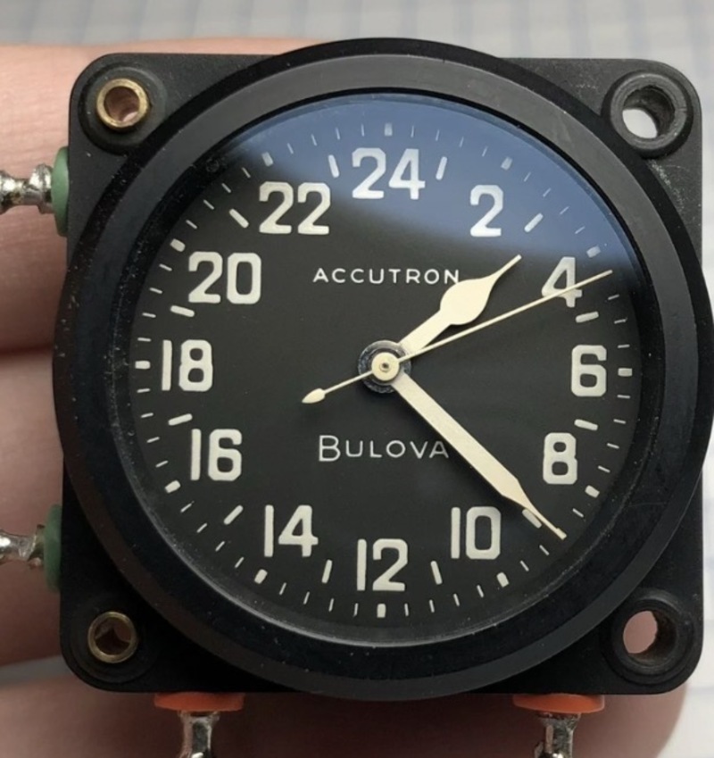
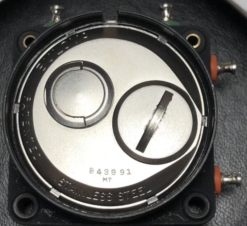
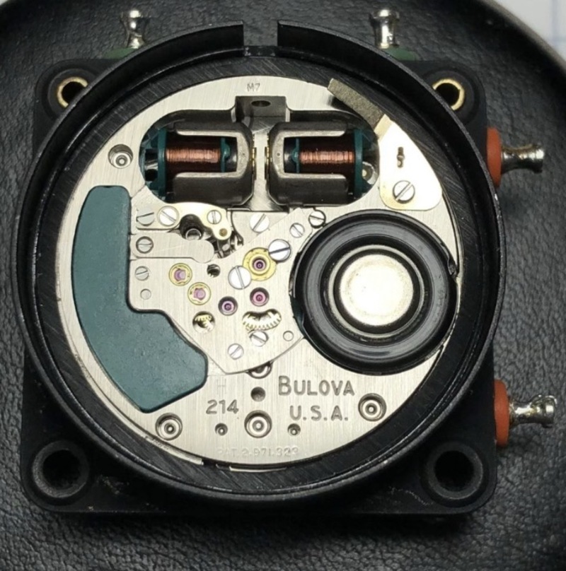
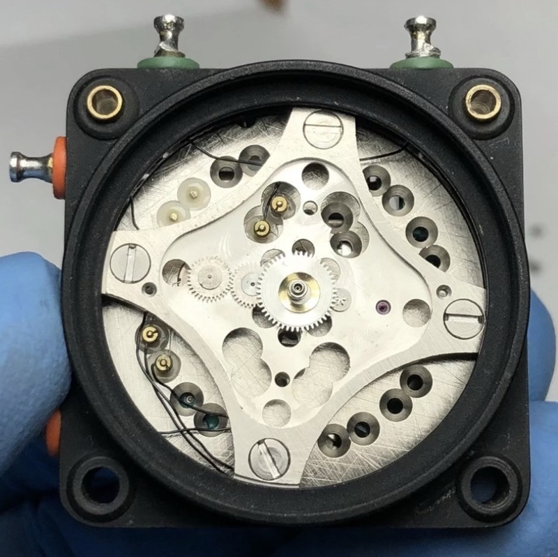
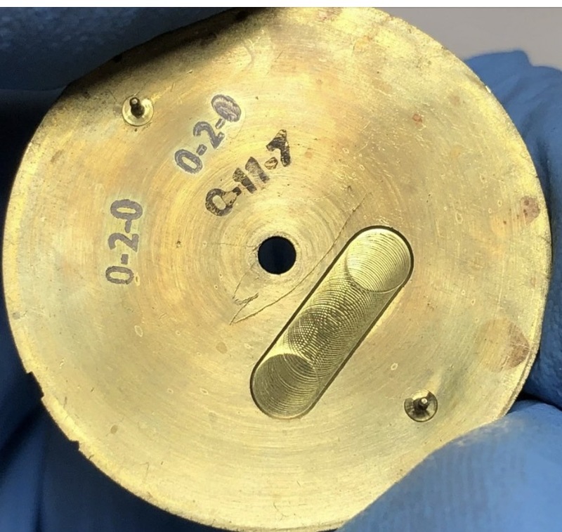
Had this for a while but this was my first chance to upload.

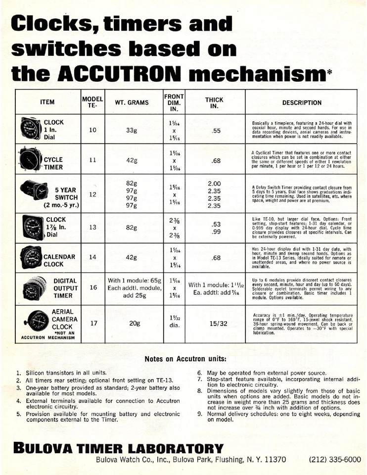
Perfect. Thank you. I just emailed this to the Admins because I couldn’t post it. You made my day. This is one of the most informative ads I’ve seen.
In reply to Perfect. Thank you. I just… by Jeff48920
I believe You have the TE-10
In reply to I believe You have the TE-10 by FifthAvenueRes…
Thanks but the 10 is a clock only. The colored boot electrical contact lugs identify it as a timer instead of a panel clock. Some of the confusion is that the 11 is often shown without either a 12 or 24 clock face while the 10 always has a clock dial. Thanks again for the interest.
In reply to Thanks but the 10 is a clock… by Jeff48920
I'm not seeing any Hour or Minute hands on the TE-11 which is listed as a cycle timer.
?
The timer looks to have 8 contact points (not sure why so many). The hands setup also seems to be more clock related. I think I agree with the TE10 model.
In reply to The timer looks to have 8… by mybulova_admin
4 separate + - wiring contacts.
1 set for each of the different timer settings depending on which is used: 1 revolution per minute, 1 revolution per hour, 1 revolution per 12 hours or 1 revolution per 24 hours.
wild guess but it makes sense.
the subject has 2 sets of contacts, it could be set as a 12 hour clock or as a 24 hr clock.
?
This is probably TMI. Please feel free to remove it if admins deem it too distracting
TE-11 Terminal Pinout & Switching Diagram
The color-coded plastic washers or sleeves at the base of each terminal pin designate their specific electrical loop behaviors. The switching mechanism interfaces with external instrumentation, telemetry equipment, or time-lapse cameras:
- Green Insulation Washers (Left Side): These two terminals form a dedicated normally open or closed physical contact switch loop. When the clock triggers internal cam intervals, this circuit opens or closes to pass signals to recording gear.
- Orange Insulation Washers (Bottom Side): These two terminals form a separate secondary switch loop completely isolated from the side terminals.
Core Technical Specifications
- Movement Base: Built around a modified Bulova Accutron 214 tuning fork caliber.
- Power Setup: The internal tuning fork and hand-drive wheel trains run continuously on the cell inside the case. If your clock is dead, it needs an internal battery replacement rather than external voltage applied to the pins.
- Function: Used strictly as a dry-contact timer mechanism. Passing external voltage directly through these terminal pins will fry the internal switch contacts or disrupt the tuning fork mechanism.
- Triggering Times and length of actuation: Preset to customer’s specifications at the factory when constructed. Cannot be adjusted.
- Testing circuitry.
- To safely test if the internal dry-contact switches on your TE-11 are successfully opening and closing, you must use your multimeter on its Continuity (or Resistance) setting.
- Because this is a dry contact, never apply external voltage from a power supply during this test. The multimeter supplies its own safe, microscopic voltage to detect if the circuit is physically connected.
- To safely test if the internal dry-contact switches on your TE-11 are successfully opening and closing, you must use your multimeter on its Continuity (or Resistance) setting.
- Step-by-Step Test Procedure
- Set Up Your Multimeter
- Turn your multimeter dial to the Continuity setting (usually indicated by a sound wave or diode symbol •)))).
- If your meter doesn't have a beep function, switch it to Resistance / Ohms (Ω) and set it to the lowest scale (e.g., 200 Ω).
- Touch your two test leads together. The meter should beep or show a reading very close to 0.0 ohms. This confirms your meter is working.
- Test Loop 1 (The Left Green Pins)
- Connect your red lead to the Top-Left pin and your black lead to the Bottom-Left pin.
- What to observe: Depending on where the clock's hands are currently positioned, the internal cam switch will be either Open or Closed.
- Open Circuit: The meter will show OL (Open Loop) and make no sound.
- Closed Circuit: The meter will beep and show a very low resistance (under a few ohms).
- Advance the Time to Trigger the Switch
- Because the TE-11 operates on a 24-hour cycle, the internal mechanical cam only closes the circuit at specific intervals (often once per hour, once every 12 hours, or once every 24 hours depending on the exact sub-model).
- Keep your multimeter leads connected to the green pins.
- Gently turn the setting crown to advance the clock hands forward manually through a full 24-hour cycle.
- The Goal: Watch and listen closely. As you rotate the hands past a specific hour marker, you should hear the multimeter suddenly beep (circuit closes) and then stop beeping after you advance past that point (circuit opens).
- Test Loop 2 (The Bottom Orange Pins)
- Move your multimeter leads to the two bottom pins surrounded by orange washers.
- Repeat the hand-advancement process.
- Note: The orange loop is completely independent of the green loop. It will likely trigger at a completely different time or interval on the 24-hour dial.
- Set Up Your Multimeter
Troubleshooting Your Results
Beeps intermittently as hands turn
Perfect. The internal mechanical switch and dry contacts are fully functional.TE-11 Terminal Pinout & Switching Diagram
The color-coded plastic washers or sleeves at the base of each terminal pin designate their specific electrical loop behaviors. The switching mechanism interfaces with external instrumentation, telemetry equipment, or time-lapse cameras:
- Green Insulation Washers (Left Side): These two terminals form a dedicated normally open or closed physical contact switch loop. When the clock triggers internal cam intervals, this circuit opens or closes to pass signals to recording gear.
- Orange Insulation Washers (Bottom Side): These two terminals form a separate secondary switch loop completely isolated from the side terminals.
Core Technical Specifications
- Movement Base: Built around a modified Bulova Accutron 214 tuning fork caliber.
- Power Setup: The internal tuning fork and hand-drive wheel trains run continuously on the cell inside the case. If your clock is dead, it needs an internal battery replacement rather than external voltage applied to the pins.
- Function: Used strictly as a dry-contact timer mechanism. Passing external voltage directly through these terminal pins will fry the internal switch contacts or disrupt the tuning fork mechanism.
- Triggering Times and length of actuation: Preset to customer’s specifications at the factory when constructed. Cannot be adjusted.
- Testing circuitry.
- To safely test if the internal dry-contact switches on your TE-11 are successfully opening and closing, you must use your multimeter on its Continuity (or Resistance) setting.
- Because this is a dry contact, never apply external voltage from a power supply during this test. The multimeter supplies its own safe, microscopic voltage to detect if the circuit is physically connected.
- To safely test if the internal dry-contact switches on your TE-11 are successfully opening and closing, you must use your multimeter on its Continuity (or Resistance) setting.
- Step-by-Step Test Procedure
- Set Up Your Multimeter
- Turn your multimeter dial to the Continuity setting (usually indicated by a sound wave or diode symbol •)))).
- If your meter doesn't have a beep function, switch it to Resistance / Ohms (Ω) and set it to the lowest scale (e.g., 200 Ω).
- Touch your two test leads together. The meter should beep or show a reading very close to 0.0 ohms. This confirms your meter is working.
- Test Loop 1 (The Left Green Pins)
- Connect your red lead to the Top-Left pin and your black lead to the Bottom-Left pin.
- What to observe: Depending on where the clock's hands are currently positioned, the internal cam switch will be either Open or Closed.
- Open Circuit: The meter will show OL (Open Loop) and make no sound.
- Closed Circuit: The meter will beep and show a very low resistance (under a few ohms).
- Advance the Time to Trigger the Switch
- Because the TE-11 operates on a 24-hour cycle, the internal mechanical cam only closes the circuit at specific intervals (often once per hour, once every 12 hours, or once every 24 hours depending on the exact sub-model).
- Keep your multimeter leads connected to the green pins.
- Gently turn the setting crown to advance the clock hands forward manually through a full 24-hour cycle.
- The Goal: Watch and listen closely. As you rotate the hands past a specific hour marker, you should hear the multimeter suddenly beep (circuit closes) and then stop beeping after you advance past that point (circuit opens).
- Test Loop 2 (The Bottom Orange Pins)
- Move your multimeter leads to the two bottom pins surrounded by orange washers.
- Repeat the hand-advancement process.
- Note: The orange loop is completely independent of the green loop. It will likely trigger at a completely different time or interval on the 24-hour dial.
- Set Up Your Multimeter
Troubleshooting Your Results
What You See/Hear: Beeps intermittently as hands turn
What It Means: Perfect. The internal mechanical switch and dry contacts are fully functional.
Next Steps: No action needed; the unit works as intended.
What You See/Hear: Stays on OL(no beep) for a full 24 hours
What It Means: Open Switch / Corrosion. The internal contacts are either dirty, oxidized, or the mechanical cam has failed.
Next Steps: Try gently tapping the side of the casing. Vintage contacts can get stuck from decades of sitting idle.
What You See/Hear: Beeps constantly (0 ohms) for a full 24 hours
What It Means: Short Circuit / Fused Contacts. The internal contacts may have sparked and welded themselves together in the past due to a high external voltage overload. The unit will require a vintage instrument specialist to open the casing and separate the contacts.
Next Steps: No action needed; the unit works as intended.
What You See/Hear: Stays on OL(no beep) for a full 24 hours
What It Means: Open Switch / Corrosion. The internal contacts are either dirty, oxidized, or the mechanical cam has failed.
Next Steps: Try gently tapping the side of the casing. Vintage contacts can get stuck from decades of sitting idle.
What You See/Hear: Beeps constantly (0 ohms) for a full 24 hours
What It Means: Short Circuit / Fused Contacts. The internal contacts may have sparked and welded themselves together in the past due to a high external voltage overload.
Next Steps: The unit will require a vintage instrument specialist to open the casing and separate the contacts.